top of page
912 56 616
contact@macrepair.no
Sørkedalsveien 82, 0377 Oslo
(Kun etter avtale)
Hjem
Tjenester
MacBook Reparasjon
Bytte skjerm Macbook
Windows PC
Spillkonsoll
PC GPU
Harddisk og minnepinne
Mobiltelefon reparasjoner
AirPods Max - flexgate
Kontakt
Lever enhet
Blogg
More
Use tab to navigate through the menu items.
Profesjonell MacBook-reparasjon
Lever eller
send in
ehnet
MacBook reparasjoner
Andre Tjenester
Windows PC/Bærbar PC reparasjoner
Ekstern harddisk og minnepinne reparasjoner
PC GPU reparasjoner
Spillkonsoll reparasjoner
Mobiltelefon reparasjoner
AirPods Max - flexgate
Vi ligger sentralt i Oslo!
Lever personlig eller send inn
Finn ut hvordan det funker
Facebook
Twitter
Pinterest
Tumblr
Copy Link
Link Copied
Play Video
Play Video
24:07
Dead Nvidia Tesla V100
Dead Nvidia Tesla V100 — one of the MOSFETs in the power stage failed and burned right through the board. This one wasn't a clean swap. The MOSFET didn't just short out, it cooked itself badly enough to punch through two layers of the PCB and take part of the copper power lines with it. So before any new part could go on, I had to clear out all the burnt, carbonized material, work out exactly which traces and inner-layer connections were gone, and rebuild the missing sections of the power delivery by hand. Once the power lines were reconstructed and the rails checked out clean, I fitted a new MOSFET and brought the card back up under load to make sure the repair actually held. These data-center cards are built like tanks, but when the power section lets go it usually takes the board with it — which is exactly what makes them worth fixing instead of binning. Reconstructing burnt power planes is one of the more satisfying parts of this kind of work. #nvidia #teslav100 #gpurepair #microsoldering #boardrepair #componentlevelrepair #pcbrepair #electronicsrepair #soldering #datacenter Død Nvidia Tesla V100 – en av MOSFET-ene i strømtrinnet havarerte og brente seg tvers gjennom kretskortet, gjennom to lag og deler av kobberbanene. Før et nytt komponent kunne settes på måtte jeg fjerne alt forkullet materiale, kartlegge hvilke baner som var borte, og rekonstruere de ødelagte delene av strømforsyningen for hånd. Etter at banene var bygget opp igjen og spenningene målt rene, satte jeg på ny MOSFET og testet kortet under last. Trenger du reparasjon av grafikkort, hovedkort eller datagjenoppretting? Komponentnivå-reparasjon (mikrolodding) i Oslo: 🔧 macrepair.no
Play Video
Play Video
20:17
Dead iPhone 16 Pro Max: No Power, No Charging - Charging IC Replacement (data recovery)
This iPhone 16 Pro Max arrived completely dead — no power, no charging, no response to anything. The owner needed the data back, not just a working phone. This is becoming a familiar story: iPhone 16 series owners are reporting phones that suddenly stop charging or won't turn on at all, often with no drop or liquid damage. In many of these cases, the fault isn't the battery or the USB-C port — it's a failed charging IC on the logic board itself, sometimes shorting the main power rail and killing the phone entirely. In this video I take you through the full board-level diagnosis and repair: ▶ Measuring current draw with a bench power supply — what a healthy board looks like vs. a dead one ▶ Using a thermal camera to find the shorted component ▶ Splitting the stacked "sandwich" logic board — and why low, slow heat matters ▶ Comparing measurements against a known-good donor board ▶ Harvesting the replacement charging IC from a donor, reballing it, and soldering it onto the customer's board ▶ First power-on and confirming all data intact Why this repair is harder on the 16 series: the stacked board design means the fault is often buried between the two PCB layers, so you can't even probe it properly until the sandwich is split — a step that can destroy the board if rushed. Apple's answer to this fault is usually a full device replacement, which means losing your data. Board-level repair saves both. 🔧 About me: I run Macrepair.no in Oslo, Norway — component-level repair and data recovery for Apple devices and GPUs. If your iPhone or MacBook is dead and the data matters, get in touch. 🌐 macrepair.no 0:00 The problem: dead iPhone 16 Pro Max 0:11 Current draw test & thermal camera 0:56 Splitting the sandwich board 3:30 Visual inspection & multimeter checks 5:51 Testing jig preparation 9:35 Found it: shorted charging IC 11:55 Harvesting the donor chip 13:28 Removing the faulty IC 16:30 Reballing & resoldering 19:06 First power-on — data recovered
Play Video
Play Video
30:32
iPhone 6s plus - no image/no backlight repair for data recovery
Play Video
Play Video
23:39
A2442 - reconstructing LCD backlight circuit
Mac wasn't properly checked after it was liquid damaged, because it worked with external screen. After 6 months part of the backlight circuit simply evaporated, all due to the corrosion that was progressing constantly.
Play Video
Play Video
38:34
Hole burned through the motherboard – A2442 M1 Max repair for data recovery
Macbook Pro M1 Max A2442 - data recovery after liquid damage. The damage on this Macbook was almost entirely concentrated in the speaker amplifier circuit — a section that handles high current, which made the short especially violent. It burned nearly all the way through the motherboard, and made a capacitor weld itself to the copper trace. I did not know the full extent of the damage so as usual - I try to not introduce new damage. So that's why I prefer to drill out welded components instead of ripping them off by force. Also, the pad reconstruction in the last part of the video is completely unnecessary — it would have been fine to just solder the resistor at an angle. I just wanted to do it that way instead. In this case, data recovery was the top priority. Getting the Mac to work again for daily use was just a bonus. To make room for the repair and reduce unnecessary risk, I removed any non-essential components. But before cutting or drilling through the board, I needed to see and understand its internal structure. While XZZ software shows all the layers and traces from the boardview, I don’t fully trust it in extreme cases like this. So I took a donor board and started physically scraping away each layer to document the exact stack-up — taking photos and recording everything as I went. In the end, I left the speaker amplifier circuit disconnected. Rebuilding it wasn’t necessary for recovery and would have added significant time and cost to the repair. The Mac now works, but with limitations: audio output and the internal microphone are permanently disabled. It must be used with external wireless sound devices — speakers or headphones — to play media or use audio features. 00:00 – Intro 02:56 – Capacitor welded to copper trace 05:03 – Preparing donor board 06:31 – Inspecting internal layers using XZZ tool 07:36 – Cutting into donor board to examine layer structure 13:37 – Removing burnt layers from the damaged motherboard 24:29 – Burn goes through the entire PCB 25:34 – Cutting into the other side of the board 28:36 – Quick test after cleaning and drying 29:11 – USB-C shows 20V – signs of life 29:34 – First proper power-on test 30:19 – Apple logo appears 30:46 – MacOS successfully boots 31:22 – One last fix 31:36 – Rebuilding a corroded pad 33:45 – Replacing a tiny but critical resistor 35:08 – Patching the hole in the board
Play Video
Play Video
01:05:45
Dead A2485 M1 Max - missing PP3V8_AON
A2485 M1 Max - missing PP3V8_AON Mosfet failure killed U8100 (343S00515) PMIC. PP3V8_AON was shorted, after removing U8100 partial short persisted. Short was detected with diode mode measurements. This video demonstrates why having a fast USB-C power meter is essential. It allowed me to detect power cycling during the initialization of later power stages, indicating a likely short on one of the main power lines. That immediately pointed me to where I should start measuring with the multimeter, significantly speeding up the diagnostic process. https://www.avhzy.com/html/product-detail/usb-c-meter-c4 https://store.avhzy.com/index.php?route=product/product&product_id=57 00:00 - Start 16:17 - Visible damage on U8100 PMIC 16:50 - Removing the PMIC 21:00 - Continuing with voltage injection to find the shorted component 22:22 - Removing PP3V8_AON controller chip 23:23 - Trying to further isolate the PP3V8_AON power line 24:25 - Extracting donor PMIC from known "good" A2442 motherboard 28:34 - Reballing the chip 55:32 - Still 5V because I forgot to put back PP3V8_AON controller
Play Video
Play Video
30:11
A2485 - 16 inch M1 Pro dead after using a cheap charger
A2485 - 16 inch M1 Pro dead after using a cheap charger
Play Video
Play Video
15:37
WD NVMe liquid damage repair for data recovery
Western Digital M.2 Nvme SSD liquid damage repair for data recovery Easiest way to recover the data is to repair or clean the pcb. The data can be read from the chip using an adapter, but without the ssd controller chip it will be just a scrambled mess. 00:00 - General inspection 00:38 - Remove and save the sticker 01:41 - Chip off 02:26 - Remove old solder 05:31 - Reballing 10:06 - Testing all the pads in diode mode 10:51 - One pad potentially shorted,, mark to check later (if chip pinout will be available) *it was not 11:27 - Putting the chip back 12:28 - I messed up and moved the chip 12:55 - Soldering the chip back 2nd time 13:58 - Check the balls 14:32 - Clean the ssd and test it
Play Video
Play Video
17:53
A2141 - PPBUS_G3H short, mac is dead - data needed
Macbook Pro 16 inch 2019 no power. Data urgently needed to be recovered, no backups were made. Short on PPBUS_G3H and blown tantalum capacitor. Even though I was soldering wires in that area - I completely missed the laminate discoloration near the capacitor. I did not look for the reasons why it failed, data needed to be recovered asap. Having a fully working (with warranty)motherboard was not a priority. Normally tantalum capacitors can fail due to various factors, including overvoltage, overcurrent, overheating, and manufacturing defects. It is highly recommended to check for overvoltage or overcurrent, and check the whole power circuit.
Play Video
Play Video
01:02:14
A2338 Macbook Pro M1 - dead after using a cheap charger
Mac A2338 Pro M1 that died after bad cheap charger was used. Both CD3217 charging controller chips had to be replaced. In this case it was not easy to determine which chip is dead, or if both were dead. LDO lines were present, and I'm not that familiar with M series power systems. Important files were on the hard drive, and they were not backed up. So because of that laptop had to be fixed on the same day - to save time I decided to blindly replace both chips. They were taken from a known good motherboard.
Play Video
Play Video
03:59:12
RTX 4070 Ti Super - cracked pcb repair
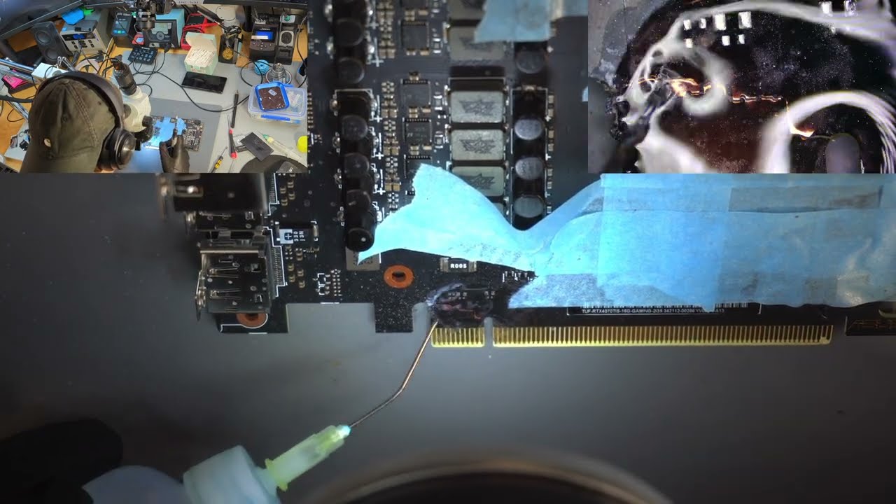
Repair of GeForce RTX 4070 Ti Super with cracked pcb - PCIe connector 00:00:00 - Dissasembly 00:07:30 - Moving components out of the way 00:09:31 - Drilling out top side crack 00:21:49 - Drilling out bottom side crack 00:31:34 - Back to top side 00:37:17 - Bottom side again 01:01:30 - Preliminary soldering 01:07:50 - First layers of UV mask 01:10:22 - Bottom side power lines reconstruction 02:00:47 - Signal traces 02:07:05 - More topside drilling 02:17:33 - Repairing signal lines 02:37:10 - Reconstructing 12V PCIe power line 02:45:41 - More power lines 03:05:56 - Grinding out the second crack 03:13:06 - Filling the spot with UV solder mask 03:18:49 - More signal traces 03:27:26 - UV mask 03:31:18 - Cleaning in 99% ISO + water 03:34:42 - Pre-drying 03:36:33 - Final layers of UV mask 03:40:16 - Reassembly 03:43:43 - Benchmarks and stress tests (BM: Wukong, max, 5K) 03:59:33 - The end #nvidia #rtx3070 #pcb #microsoldering #repair #soldering #gpu
Play Video
Play Video
20:42
Macbook Touch ID button repair
The Touch ID button despite being seemingly small and inexpensive part - has to be repaired. This repair was the part of a whole process of macbook repair after liquid damage. If Touch ID button would be simply replaced - the touch ID would never work again. Every button is married to the motherboard and has to be purchased from apple (not always possible) and calibrated via special process. Other option that is much less expensive is the repair of the connector.
Play Video
Play Video
05:03
A2141 - no power, data has to be recovered
A2141 820-01700 - no power, 5V 0amps on USB C Data recovery was the priority It had some corrosion near SSD PMIC U9580. I discovered a short on PPBUS_G3H_SSD0_SNS. After removing some components and testing, I determined the PPBUS_G3H was shorted. Best way to pinpoint shorted component on this line is voltage injection. I start with 1V, when nothing triggers I take it up to 3V. Saw a speaker amplifier chip heat up, and after removing it I noticed it had a burned spot underneath, not sure if it was corrosion. But from what I have seen - speaker amplifier chips very often have corrosion under them. I guess they are near the edge and accumulate dust under them, and moisture doesn't go away that fast when there's dust. Those chips also operate with higher voltages - 12V, near lower voltage line - so they get burned easily.
Play Video
Play Video
16:26
No backlight - Macbook Pro Retina A1502 2015
Macbook A1502 that has no backlight. I started to suspect the no backlight issue when testing it earlier, power consumption was within norm, but screen was dark. And those models are notorious for having lcd backlight issues. The culprit is usually backlight driver chip U7700. This is supposedly cause by poor factory soldering together with non leaded solder. This time I also found a tiny speck of corrosion on one of eDP display connector data lines. I am not sure if this was causing the problem, since data line was not broken. Did not bother figuring out which one was at fault, I just reworked both places. (I forgot to unpause recording when lifting the U7700, but nothing important is missing, I put it back almost right away.) Macbook A1502 som ikke har bakgrunnsbelysning. Jeg begynte å mistenke problemet uten bakgrunnsbelysning da jeg testet det tidligere, strømforbruket var innenfor normen, men skjermen var mørk. Og disse modellene er beryktet for å ha problemer med LCD-bakgrunnsbelysning. Synderen er vanligvis baklysdriverbrikken U7700. Dette er visstnok forårsaket av dårlig fabrikklodding sammen med blyfri loddemetall. Denne gangen fant jeg også en liten flekk av korrosjon på en av eDP-skjermkontaktens datalinjer. Jeg er ikke sikker på om dette var årsaken til problemet, siden datalinjen ikke var ødelagt. Gidder ikke finne ut hvilken som var feilen, jeg bare omarbeidet begge steder. (Jeg glemte å stanse opptaket når jeg løftet U7700, men ingenting viktig mangler, jeg satte det tilbake nesten med en gang.)
Play Video
Play Video
36:19
Macbook Pro A1708 flexgate repair
This is not a instructional video, this is how I do this repair. There are couple different techniques, this is how I chose to do it. Flexgate is what we call the manufacturing defect most commonly seen on 13 inch A1706/A1708 2016 Macbook pro. Also 15 inch model is often affected. More information: (https://logi.wiki/index.php/A1706/A1708_TConn_Backlight_Pinout_(FlexGate)) The backlight cable was made 0.5-1mm too short(just guessing) and this is causing too much strain put on it, and the cable starts to break off near the connector. Whenever its possible I choose to harvest cables from broken lcds. Only macbook pro lcds are suitable. I take cables that are pristine, not coming from models affected by the defect. You can buy new cables on aliexpress, but I really don't like the quality of those. They are not as precisely manufactured, they're kinda dog water quality. Even though suppliers always say they're original (they are not) Obviously I have to scrape off the paint to be able to start soldering, I always tin cables before cutting. This allows for a cleaner and nicer cut. LCD side cable is tinned and then tin is wicked off. I mirror the traces on the cables and I kind of flip the cable upside down and then bend it on itself. Lastly I make a cut in the wifi antenna, to make more space - so my spliced cables, that is 3-4 times thicker now. I bend it on itself and its two cables one on top of the other, then comes the tape. So I dont want the cable to keep brushing against the wifi antenna, the tolerance there is super small. Cutting off a bit of plastic solves that problem and it does not affect wifi performance in any way(I only cut plastic and tiny piece of metal shielding(?)) I always give warranty on those repairs. https://www.macrepair.no 00:00 - Start 00:35 - Double checking if its the flexgate 01:07 - Image present but no backlight 01:19 - Disassembling the mac 05:09 - Backlight connector completely broken off 06:06 - Harvesting a good cable from a broken lcd 07:35 - Finding a good spot for cuts and for scraping the mask 10:25 - Preparing screen side cable 14:55 - Preparing donor cable 19:20 - Tinning the cable 24:20 - Soldering two cables together 27:27 - Testing 31:28 - Securing the cable 33:31 - Modifying wifi antenna NO: Dette er ikke en instruksjonsvideo, dette er hvordan jeg gjør denne reparasjonen. Det er et par forskjellige teknikker, dette er hvordan jeg valgte å gjøre det. Flexgate er det vi kaller produksjonsfeilen som oftest sees på 13-tommers A1706/A1708 2016 Macbook pro. Også 15 tommers modell er ofte berørt. Mer informasjon: (https://logi.wiki/index.php/A1706/A1708_TConn_Backlight_Pinout_(FlexGate)) Bakgrunnsbelysningskabelen ble gjort 0,5-1 mm for kort (bare å gjette) og dette forårsaker for mye belastning på den, og kabelen begynner å bryte av nær kontakten. Når det er mulig velger jeg å høste kabler fra ødelagte LCD-skjermer. Bare macbook pro lcd-er er egnet. Jeg tar kabler som er uberørte, som ikke kommer fra modeller som er berørt av defekten. Du kan kjøpe nye kabler på aliexpress, men jeg liker virkelig ikke kvaliteten på de. De er ikke så nøyaktig produsert, de er litt av hundevannskvalitet. Selv om leverandører alltid sier at de er originale (det er de ikke) Det er klart jeg må skrape av malingen for å kunne begynne å lodde, jeg fortinner alltid kabler før kapping. Dette gir et renere og penere snitt. LCD-sidekabelen er fortinnet og deretter blir tinn av. Jeg speiler sporene på kablene og vipper kabelen på en måte opp ned og bøyer den på seg selv. Til slutt lager jeg et kutt i wifi-antennen for å få mer plass - så de skjøtede kablene mine, som er 3-4 ganger tykkere nå. Jeg bøyer den på seg selv og de to kablene den ene oppå den andre, så kommer tapen. Så jeg vil ikke at kabelen skal fortsette å børste mot wifi-antennen, toleransen der er veldig liten. Å kutte av litt plast løser det problemet, og det påvirker ikke wifi-ytelsen på noen måte (jeg kutter bare plast og en liten bit av metallskjerming(?)) Jeg gir alltid garanti på disse reparasjonene.
Play Video
Play Video
30:19
A1708 no power - blown up tantalum capacitor
Macbook died by itself. I start diagnostics as usual with a power meter. ***never do that in case of liquid damage, open and inspect the device first*** Mac is taking 19V and 0 amps, this tells me that there might be a short in one of the main power lines, since it got to asking charger for 20V - its probably not the charging port or CD3215 issue. Then I start measuring main voltage lines, I see that PPBUS_G3H is 0.0V I'm thinking that there's no way its shorted, it cannot be this simple, it never is. With battery and power disconnected I check resistance of PPBUS_G3H and there's a dead short to ground. Okay, lets take out the motherboard then. And there is a burn mark on the keyboard backlight cover. Keyboard and kb backlight are safe, in this model there is a solid piece of pcb between the logic board and the plastic parts of the keyboard. Backlight is integrated into the keyboard, the infamous over designed butterfly keyboard design. On the motherboard we have blown up tantalum capacitor, I swear I have never seen that, I have seen people on YouTube get easy jobs like this, but it never happened to me. Rest of the repair is pretty straightforward - *see bad = replace bad* Extra care has to be taken when using hot air near other tantalum caps, so I cover them with 2-3 layers of thermal tape. And because of the violent nature of the failure - capacitor slightly welded itself to the motherboard. Sometimes temperatures during short circuits get so high, even the copper can melt. Voltage of this power line never exceeds 13V, not sure about potential amperage. I don't care about the donor board, I just want to extract the component as fast as possible. So I'm not covering the capacitors on donor board with anything. When replacing burned components always check why they might have blown up. In this case I only check if the short persists - tantalum capacitors just die sometimes. They also deteriorate with age. Of course there will be time spent stress testing the device, the actual repair is only a part of the process. På 4-5 år har jeg aldri hatt en jobb som dette, hvor skaden ville være så åpenbar. Vel, med mindre det er væskeskade. Men så er skaden ikke bare åpenbar, men det er mye mer skade, og som ekstra er det skader som ikke er synlige. Det er fint å få en slik reparasjon mellom jobbene jeg bruker 5-10 timer på, noen ganger uten å finne en løsning eller finne ut at det ikke kan fikses. Macbook døde av seg selv. Jeg starter diagnostikk som vanlig med strømmåler. ***gjør aldri det i tilfelle væskeskade, åpne og inspiser enheten først*** Jeg ser at den tar 19V og 0 ampere, dette forteller meg at det kan være en kortslutning i en av hovedstrømledningene, siden den måtte be laderen om 20V - det er sannsynligvis ikke ladeporten eller CD3215-problemet. Så begynner jeg å måle hovedspenningslinjer, jeg ser at PPBUS_G3H er 0,0V. Jeg tenker at det ikke er mulig at det er kortsluttet, det kan ikke være så enkelt, det er det aldri. Med batteri og strøm frakoblet sjekker jeg motstanden til PPBUS_G3H og det er en død kortslutning til jord. Ok, la oss ta ut hovedkortet da. Og det er et brennmerke på tastaturets bakgrunnsbelysningsdeksel. Tastatur og kb-bakgrunnsbelysning er trygge, det er et solid stykke PCB. I denne modellen er bakgrunnsbelysning integrert i tastaturet, beryktet over designet sommerfugltastatur. Og på hovedkortet har vi sprengt tantalkondensatorer, jeg sverger at jeg aldri har sett det, jeg har sett folk få enkle jobber som dette, men det skjedde aldri med meg. Resten av reparasjonen er ganske grei - *se dårlig = erstatt dårlig* Ekstra forsiktighet må utvises når du bruker varmluft i nærheten av tantalhetter, så jeg dekker dem med 2-3 lag termisk tape. Og kondensatoren var veldig svakt sveiset til hovedkortet. Noen ganger blir temperaturene under kortslutninger så høye at til og med kobberet kan smelte noen ganger. Og spenningen til denne kraftledningen overstiger aldri 13V. Jeg bryr meg ikke om giverstyret, jeg vil bare trekke ut komponenten så raskt som mulig. Når du bytter ut brente komponenter, må du alltid sjekke hvorfor de kan ha sprengt. I dette tilfellet sjekker jeg bare om det korte vedvarer - tantalkondensatorer begår noen ganger bare seppuku. De forverres med alderen. Selvfølgelig vil det bli brukt tid på å stressteste enheten, selve reparasjonen er bare en del av prosessen.
Play Video
Play Video
01:06:37
A2141 Macbook Pro 16-inch - liquid damage and a dead screen. 800$ lcd saved
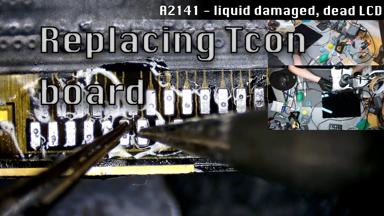
Macbook Pro 16 inch 2019 A2141 820-00170 Liquid damage, lots of corrosion on the motherboard. Discovered corrosion on lcd controller board - tcon board. Corroded connector and most likely corrosion under the shields. Trying to fix the tcon is often counter productive. Very high risk of doing even more damage and potentially damaging or partially desoldering the cables. These cables are really hair thin, maybe 0.1mm. The pads on the cables get damaged if you even look at them in wrong way. One bad move and the cable is gone. Don`t ask me how I know.. Normally when extracting the tcon I would not waste so much time, but I thought that I might need this broken lcd later, idk. It is important to take your time, very carefully peel off all the stickers, especially if you are preparing the receiving lcd cables. I add leaded solder to make desoldering cables easier, but this step probably can be skipped entirely. I'm using lowest possible temperature, around 330 C. Same with hot air - 320-330 C. When preparing donor tcon I try to make sure there is as little solder as possible on those pads. Its also important to not use too much flux, and use a thin one. This helps later when you need to see if the pads are soldered on properly. Thicker flux would cover the pcb and I would not be able to see under the cable(its kinda translucent) You can probably use hot air to do this fast, but I prefer to solder the pads one by one, to have more control over whats happening. 330-340 C. Later I switched to a different tip shape (chisel) that I had in my JBC station, to solder ground pads better. Conical type tip does not work very well in this situation. During the whole process I'm being EXTREMELY careful when moving the screen or repositioning the tcon board. As I said previously, one wrong move and the cable is gone. There is no do overs, no second chances. If cable is damaged - then it has to be replaced by disassembling the lcd completely. Which is a total nightmare and I absolutely hate doing that. I skipped the part where I secure the soldering area with one sided tape, and put back those plastic thingies. 00:00:00 - Showing the damage 00:03:58 - Lid angle sensor is corroded 00:05:37 - Basic tests to confirm the lcd(tcon) is dead 00:07:14 - Testing with a broken(but working) lcd 00:09:02 - Preparing for tcon extraction 00:13:51 - Tinning the pads with leaded solder 00:19:04 - Desoldering the cables with hot air 00:21:43 - Wicking all of the old solder 00:24:58 - Desoldering the bad tcon 00:38:55 - The cables are hair thin 00:39:26 - Preparing the tcon 00:45:23 - Soldering the cables 01:02:30 - Testing the screen 01:06:08 - Everything works Macbook Pro 16 tommer 2019 A2141 820-00170 Væskeskader, mye korrosjon på hovedkortet. Oppdaget korrosjon på lcd-kontrollerkort - tcon-kort. Korrodert kontakt og mest sannsynlig korrosjon under skjoldene. Å prøve å fikse tcon er ofte kontraproduktivt. Svært høy risiko for å gjøre enda mer skade og potensielt skade eller delvis avlodde kablene. Disse kablene er veldig tynne i håret, kanskje 0,1 mm. Putene på kablene blir skadet hvis du til og med ser på dem på feil måte. Ett dårlig trekk og kabelen er borte. Ikke spør meg hvordan jeg vet det.. Normalt når jeg trekker ut tcon, ville jeg ikke kaste bort så mye tid, men jeg tenkte at jeg kunne trenge denne ødelagte LCD-en senere, idk. Det er viktig å ta deg god tid, trekk forsiktig av alle klistremerkene, spesielt hvis du klargjør mottaks-lcd-kablene. Jeg legger til blyloddet for å gjøre avlodding av kabler enklere, men dette trinnet kan sannsynligvis hoppes over helt. Jeg bruker lavest mulig temperatur, rundt 330 C. Samme med varmluft - 320-330 C. Når jeg forbereder donor tcon prøver jeg å sørge for at det er så lite loddetråd som mulig på disse putene. Det er også viktig å ikke bruke for mye fluss, og bruke en tynn. Dette hjelper senere når du skal se om putene er loddet på riktig. Tykkere fluks vil dekke PCB-en, og jeg ville ikke kunne se under kabelen (den er ganske gjennomsiktig) Du kan sikkert bruke varmluft for å gjøre dette raskt, men jeg foretrekker å lodde putene én etter én, for å ha mer kontroll over hva som skjer. 330-340 C. Senere byttet jeg til en annen spissform (meisel) som jeg hadde i JBC-stasjonen min, for å lodde jordputer bedre. Spiss av konisk type fungerer ikke særlig godt i denne situasjonen. Under hele prosessen er jeg EKSTREMT forsiktig når jeg flytter skjermen eller flytter tcon-tavlen. Som jeg sa tidligere, ett feil trekk og kabelen er borte. Det er ingen overs, ingen andre sjanser. Hvis kabelen er skadet - må den skiftes ut ved å demontere LCD-en fullstendig. Noe som er et totalt mareritt, og jeg hater absolutt å gjøre det. Jeg hoppet over delen der jeg fester loddeområdet med ensidig tape, og satte tilbake plastsakene.
Play Video
Play Video
01:32:01
Macbook Air M2 - A2681 liquid damage repair
Repair of Macbook Air M2 A2681 motherboard that sustained liquid damage. Pretty straightforward repair, all damage was visible and I had to simply replace all damaged components. I'm starting with cutting metal shielding on the donor board, both to have better access to components and see how difficult will it be to cut it off. Its important to have very high quality cutting tool. Then I also cut as little of the metal shielding (or the metal mounting for the heatsink) on the board I'm going to fix. Lots of components are very close to that or under it.
bottom of page